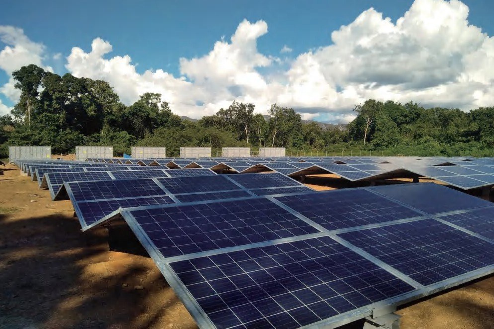
On-grid system
Solar DC is converted into AC to supply the load and connect to the grid; excess electricity may be exported subject to system settings and local requirements.
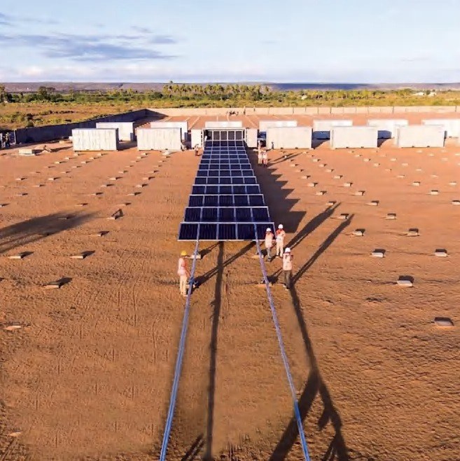
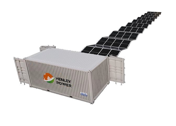
A mobile solar power system built for rapid deployment.
A maritime-standard container integrates foldable frames, rail and rack systems, inverters and optional energy storage equipment into a modular solar power solution designed for transportability, fast installation and flexible use.
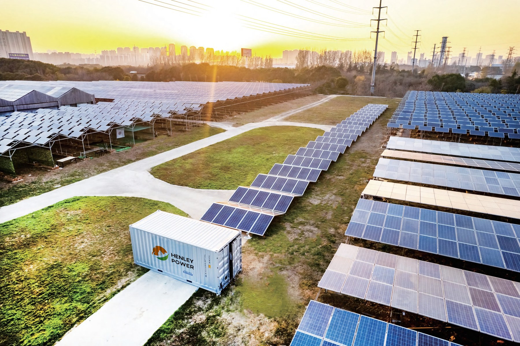
The Solar Power Container uses a customized, maritime-standard container as its carrier. Foldable frames, rail and rack systems and power-conversion equipment are integrated for modular transport, rapid deployment and straightforward maintenance.
The product range is designed for electricity-constrained or remote environments, temporary infrastructure and projects where a fixed solar station may be difficult to deploy or relocate.
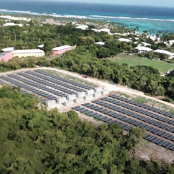
The source material highlights a modular platform for movable renewable power. Feature descriptions below follow the supplied Solar Power Container brochure.
When connected with a diesel generator, solar generation can reduce daytime engine operation, helping lower fuel use, operating costs and CO₂ emissions.
Container-based integration brings the foldable array and related power equipment into a modular unit that can be transported as a system.
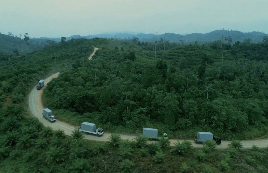
Designed for project environments where the power system may need to be relocated instead of remaining at a fixed site.
Foldable structures and modular equipment aim to simplify installation and shorten on-site construction procedures.
Solar generation offers a renewable power source for remote facilities, temporary works and energy-constrained applications.
The brochure describes a modular system that can be expanded or configured for different output requirements.
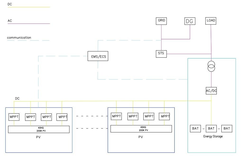
Choose a mode to see the corresponding architecture diagram and a summary based on the brochure.
Solar modules generate DC power, which is converted into AC by the inverter and supplied to the load while connected to the utility grid. Excess electricity may be exported to the grid, depending on the project configuration.
Comparison values below are transcribed from the supplied brochure's technology comparison page.
| Technical index | Movable solar power container | Traditional solar station |
|---|---|---|
| Field deployment time | 1–2 days | 10–15 days |
| Implementation installers | 4–6 persons | 6–10 persons |
| Turnover / reuse | Transferable; brochure states reusable up to 10 times a year | Fixed use; not transferable |
| Installation difficulty | Plug-and-play; modular assembly | Complex construction procedure |
| Modular portability | Readily transferable | Fixed position |
| Environmental impact | Designed to be less affected by site relocation limits | Brochure notes exposure to climate and disaster impacts |
These are brochure comparisons, not guaranteed project outcomes. Actual deployment time and labor requirements depend on site, permitting, civil works and system configuration.
The brochure outlines grid-connected, independent off-grid and autonomous microgrid / hybrid architectures.
Solar DC is converted into AC to supply the load and connect to the grid; excess electricity may be exported subject to system settings and local requirements.
An independent power system that does not rely on utility-grid power. Solar generation supplies the electrical load with the selected conversion and storage equipment.
A coordinated system that can connect to the external grid or operate in isolation, integrating solar, battery storage, conversion equipment, loads and, where required, a diesel generator.
Application scenarios listed in the brochure include remote sites, industrial facilities, infrastructure and emergency use.
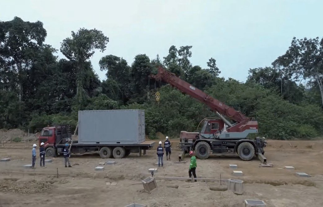
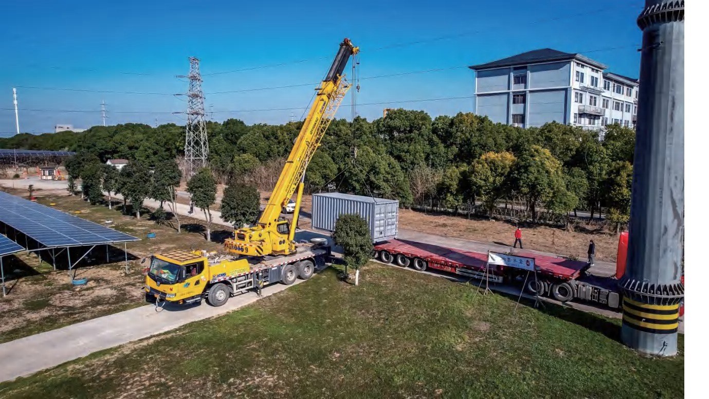
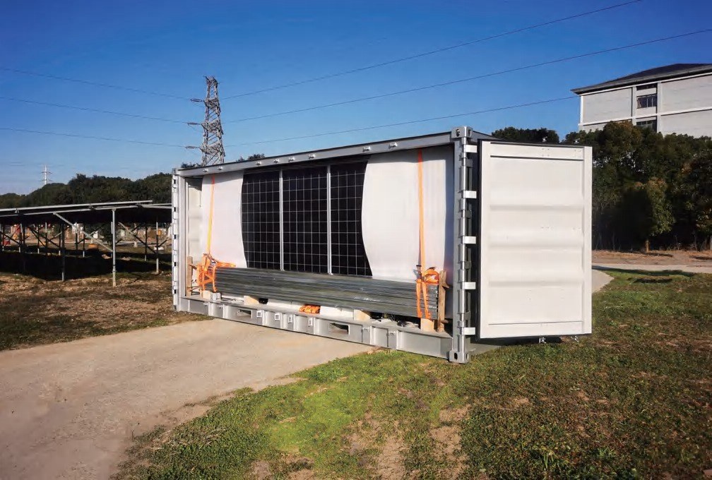
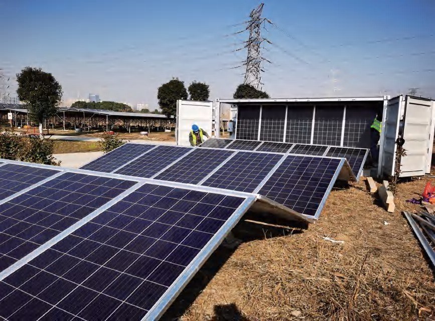
The six steps below retain the sequence and captions used in the supplied product brochure.

Core system-level data transcribed from the individual model specification pages (PDF pages 5–7).
| Parameter | SC08GP-M-20K | SC10GP-M-40K | SC20GP-M-80K | SC20HQ-M-100K | SC40GP-M-160K | SC40HQ-M-200K |
|---|---|---|---|---|---|---|
| Solar array capacity | 20 kWp | 42 kWp | 84 kWp | 105 kWp | 169 kWp | 209 kWp |
| Container type | 8GPF | 10GP | 20GP | 20HQ | 40HQ (GP Plus Height) | 40HQP (HQ Plus Height) |
| Container dimensions (L×W×H) | 2900×2260×2200 mm | 2991×2438×2591 mm | 6058×2438×2591 mm | 6058×2438×2896 mm | 12192×2438×2896 mm | 12192×2438×3100 mm |
| Container weight | 1.6 t | 2.2 t | 3.2 t | 4 t | 7 t | 8 t |
| Total system weight | 5 t | 8 t | 12.5 t | 15 t | 25 t | 30 t |
| Solar module / quantity | 595 Wp × 34 | 480 Wp × 88 | 480 Wp × 176 | 595 Wp × 176 | 480 Wp × 352 | 595 Wp × 352 |
| String inverter configuration | 20 kW × 1 | 40 kW × 1 | 100 kW × 1 | 100 kW × 1 | 80 kW × 2* | 100 kW × 2 |
| Occupied area (as stated) | 112.4 m² | 276.3 m² | 558 m² | 650.4 m² | 1108 m² | 1300 m² |
| Complete unfolding time | 60 min | 80 min | 120 min | 120 min | 180 min | 180 min |
| Complete folding time | 50 min | 60 min | 80 min | 80 min | 120 min | 120 min |
| Installation personnel | 4 | 4 | 4 | 4 | 6 | 6 |
* The SC40GP-M-160K system summary lists an 80 kW × 2 configuration, while its individual inverter specification page lists 100 kW inverter data. This source-document inconsistency must be confirmed against the final model datasheet. Other values also follow the supplied brochure; refer to the final specification or actual product configuration for engineering and purchasing decisions.
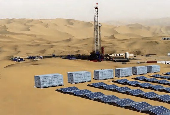
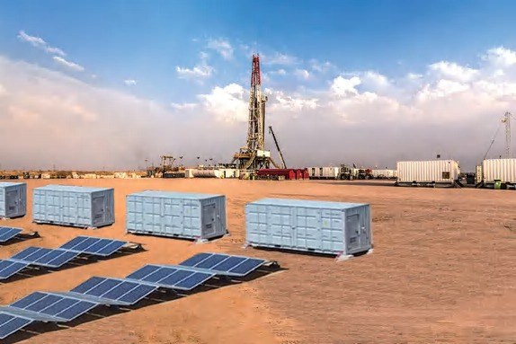
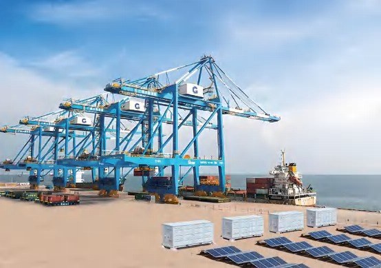
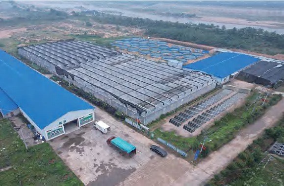
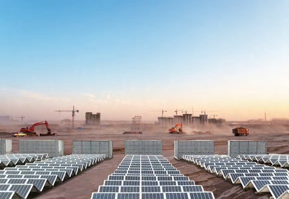
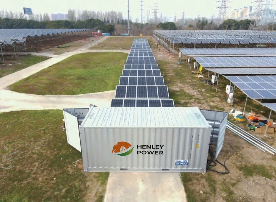
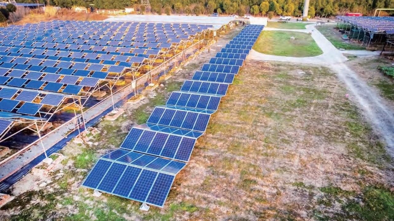
Selected project and solar-site images extracted from the supplied brochure.